Before you start
You need two things: the DXF drawings of the parts you want to cut, and the sheet sizes you stock. If your parts only exist as 3D models, you do not need a CAD seat to flatten them. See STEP to DXF flat pattern.
A word on the drawings themselves, because this is where most nesting trouble starts: each part should be a closed outline. Gaps between line ends, outlines drawn twice on top of each other, and stray construction geometry all make a nester behave strangely, because it cannot tell what the part actually is. If a part comes in looking wrong, the drawing is the first place to look.
1. Import your DXF drawings
Add the DXF files for the parts in the job. Each one becomes an entry in the part list, and its true outline, not its bounding box, is what gets packed. Internal holes come in with it, which matters later: they are usable space.
2. Set quantities and mirrored copies
You almost never need one of each. Enter how many of each part the job calls for. Where a left-hand and a right-hand version come off the same drawing, ask for mirrored copies rather than importing a second, flipped file.
Get this right before you nest rather than after. Quantities change which sheet size packs best, so changing them later means nesting again anyway.
3. List the sheet sizes you stock
Enter the stock sizes you actually have on the rack, not the sizes you could order. If you stock several, list them all: the densest packing is often not on the largest sheet, and letting the nester choose is one of the easiest savings available.
Save the list as a preset. Your stock rarely changes, so this should be one click on every job after the first.
4. Set part spacing and sheet margin
Part spacing is the gap left between neighbouring parts. It has to cover the kerf your machine actually cuts (the width of material the beam or arc removes) plus a margin for heat and small positioning errors. Too tight and parts come out undersized or tack themselves to a neighbour; too generous and you are paying for air.
Sheet margin keeps parts clear of the extreme edge, where clamps, rails and slat supports live. If you are not sure what your table needs, measure it once and reuse the number forever.
5. Run the nest
Start the nest and let it work. It packs parts by their real outline, tries rotations, drops smaller parts into the internal holes of larger ones, and, if you listed more than one stock size, picks the sheet that packs densest. Jobs of several hundred parts finish in seconds rather than minutes.
When a job does not fill the last sheet, the leftover is worth keeping as one clean piece you can put back on the rack, rather than an awkward offcut. That is a setting, not an accident.
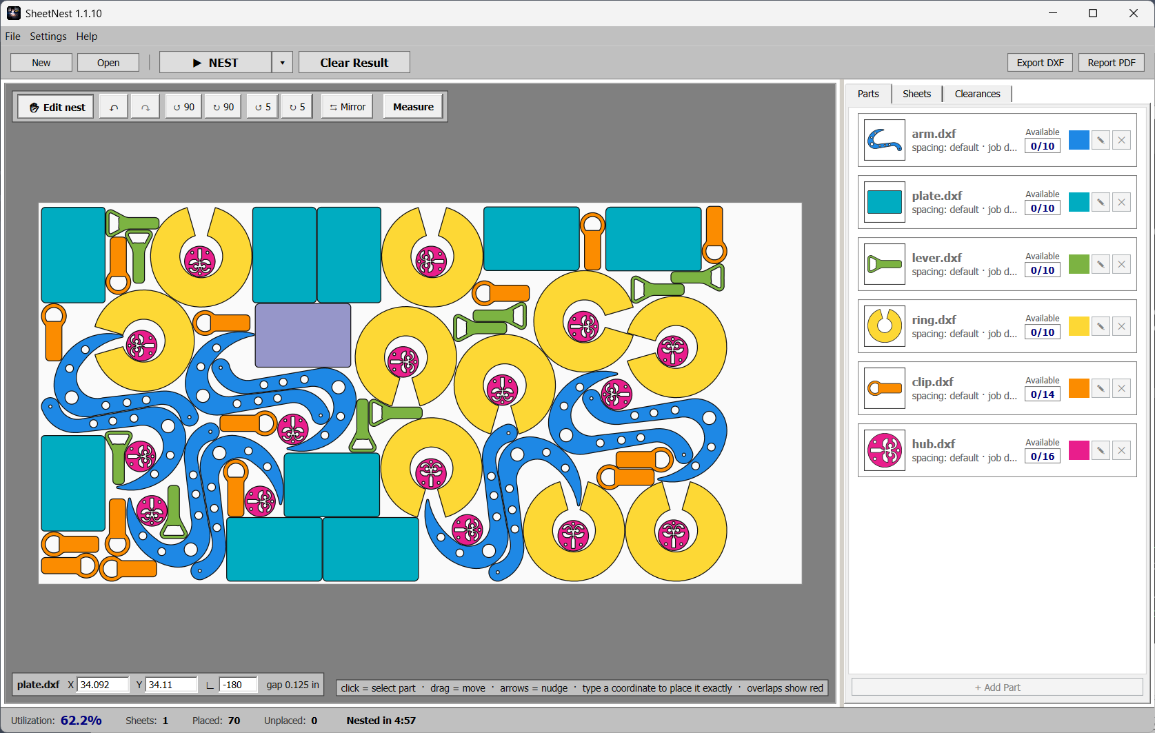
Automatic first, then take over: the finished nest is fully editable.
6. Adjust the layout by hand
Automatic nesting gets you most of the way. You know things it does not: that this part is going to warp, or that you want the big blank near the edge you will grab first. So the layout is editable:
- Select, drag, rotate and mirror any part.
- Drop a part to contact, so it settles at exactly your spacing instead of wherever you let go of the mouse.
- Snap two matching parts onto a shared common line, so one cut does both edges.
- Nudge with the arrow keys for fine positioning.
- Undo and redo freely; nothing here is a one-way door.
Spacing is enforced while you drag, so a hand-placed part cannot end up closer to its neighbour than you allowed in step 4.
7. Export a cut-ready DXF and the PDF report
Export one DXF per sheet layout. It contains the parts and nothing else: no annotations, no construction lines, no duplicated outlines. The CAM software you already use has nothing extra to trip over. From there you apply lead-ins, kerf compensation and cut order the way you always do.
The PDF report is the other half of the output, and it is the one purchasing cares about: how many sheets of each size the job needs, total area, part totals, the cutting plan, and a scaled drawing of every layout. Useful for quoting before you commit to a price.
Download SheetNest for WindowsCommon problems
A part nests as a solid block, ignoring its hole
The internal outline is probably not closed, so it is not being read as a hole. Check the drawing for a gap where two lines nearly meet.
Parts come out slightly small after cutting
That is kerf, not nesting. The cut removes material either side of the line. Kerf compensation belongs in your CAM software; part spacing in the nest only stops neighbours from interfering.
The nest looks loose
Check part spacing first. A value meant for millimetres typed into an inches job will blow every gap wide open. After that, look at whether you have given the nester room to work: one part shape at one quantity has very little to optimise.